
Return to MODULE PAGE
Iris 1.2 Assembly Instructions
STEP 1: Video |
Step 1: Attach circular pivot post adapter to base. Make sure the screws line up with the holes drilled in the base and the dimples on the plastic piece face up. Take care not to overtighten the screws. |
STEPS 2-4: Video |
|
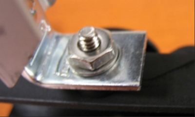
Step 2: Put long hex bolt through the hole in the base from the bottom. It should stick out of the top of the circular piece you just attached. |
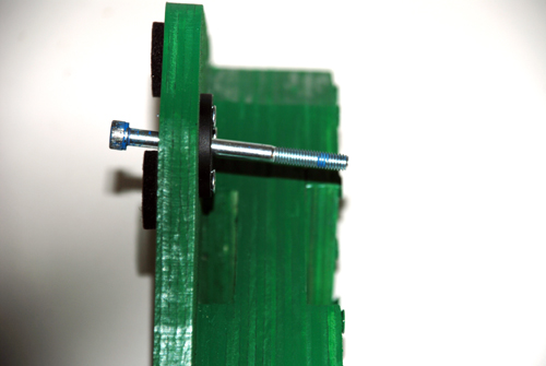 |
| Step 3: Attach the cylindrical pivot post piece to the circular pivot post adapter. The protrusions from the cylinder should fit in the holes on the circular piece. | 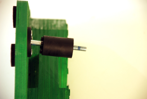 |
| Step 4: Attach the top part of the pivot post to the rest of the assembly. Tighten everything down with a 3/16” or 5mm hex wrench. | 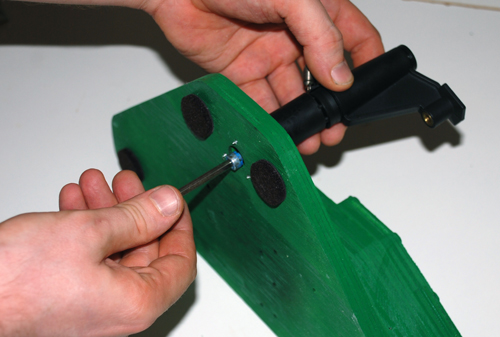 |
STEPS 5-6: Video |
|
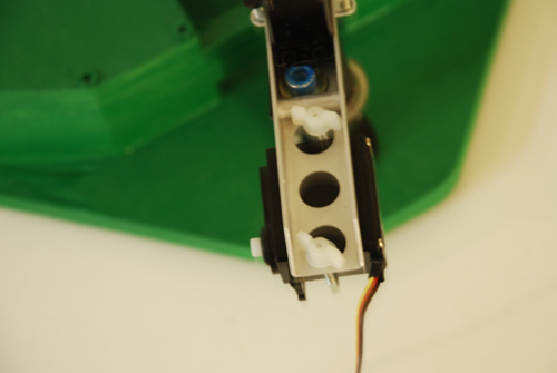
Step 5: Place the 6-hole link on the top of the pivot post, open end up, as shown in the above photo. |
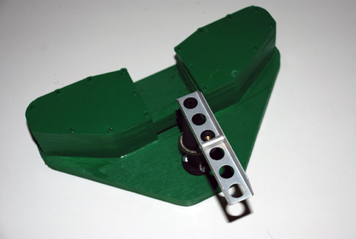 |
| Step 6: Screw the short bolt into the pivot post. Add a washer between the bolt and the metal link so it holds snugly. | 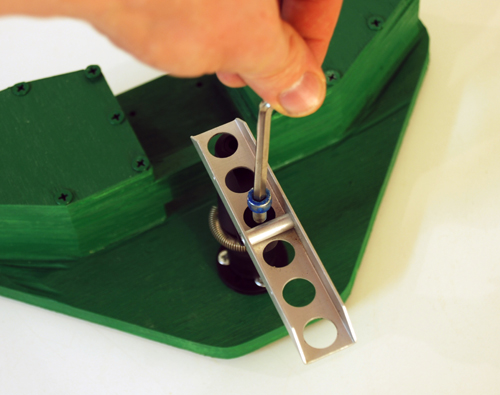 |
STEPS 7-8: Video |
|
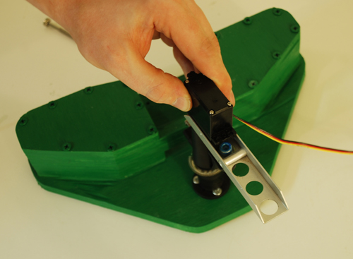
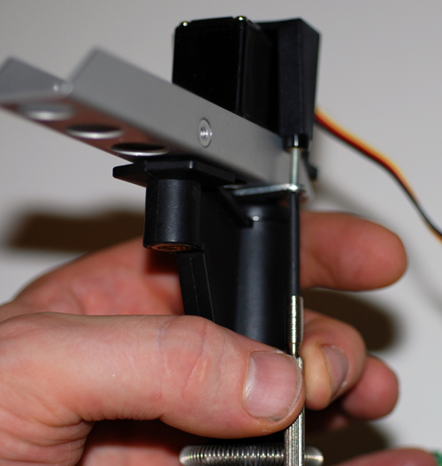
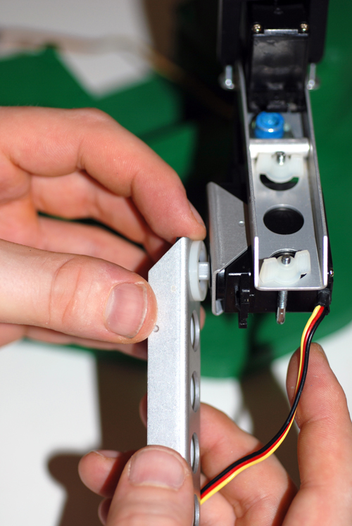
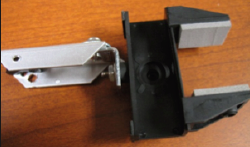
Step 7: Insert the High-Torque servo, labeled HS-645MG into the back hole of the 6-hole support. The white gear drive should fit inside the hole of the plastic base piece. |
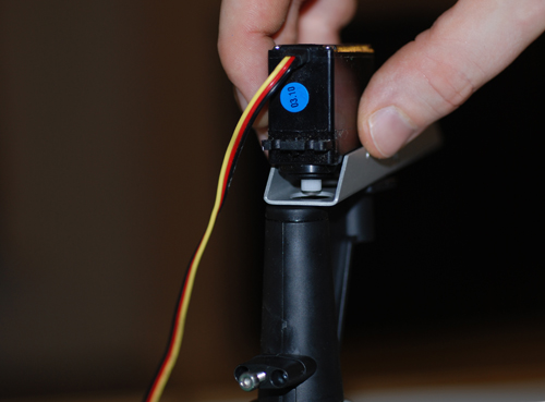 |
| Step 8: Wrap the plastic cradle around the servo, and feed the attached metal bracket underneath the metal link. Tighten the screws. | 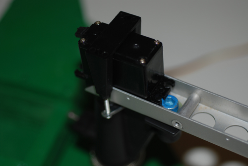
 |
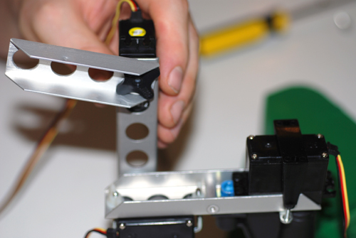
STEPS 9-10: Video |
|
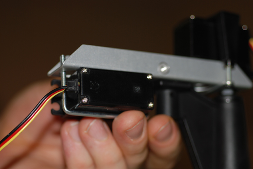
Step 9: The next piece you will attach is a standard HS-422 servo. You will need the metal cradle and the two plastic wing nuts to complete this step. |
 |
| Step 10: Place the 2-hole metal link over the servo you just attached. | 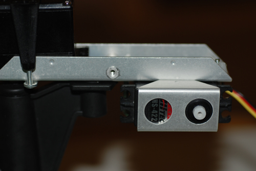 |
STEPS 11-12: Video |
Steps 11-12: Attach the 5-hole link to the servo you just attached. Put a nylon washer between the two metal links. Tighten the screw. Again, rotate the servo to make sure it has an even motion up and down. |
|
|
STEPS 13-15: Video |
|
Step 13: Add another HS-422 Servo to the other end of the 5-hole link. |
|
| Steps 14-15: Following the same steps as before, attach the 4-hole arm link, nylon washer, servo connector and servo to the previous assembly. |
|
STEPS 16-19: Video |
||
Steps 16-17: Put long hex bolt through the hole in the base from the bottom. It should stick out of the top of the circular piece you just attached. |
|
|
| Step 18: Attach the cylindrical pivot post piece to the circular pivot post adapter. The protrusions from the cylinder should fit in the holes on the circular piece. |
|
|
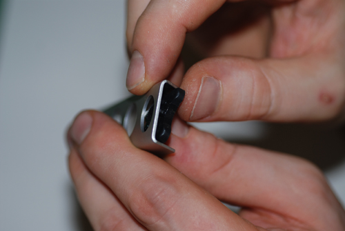
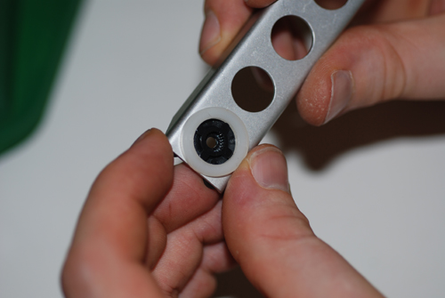
| Step 19: Attach the gripper hand to the link using a small washer and a nut. Your assembly should look like the one above. |
|
|
STEPS 20-21: Video |
|
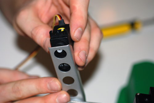
Step 20: Now attach the gripper assembly to the rest of the arm as shown, using the nylon washer and servo connector. |
|
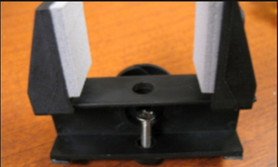
| Step 21: Attach the last servo motor into the gripper hand as shown. Make sure the arm opens and closes correctly. Note: This servo sits in the gripper hand without a screw. |
|
The remaining instructions BELOW have only images and text without videos.
|
|
Step 22 |
|
Step 23 |
|
Step 24 |
|
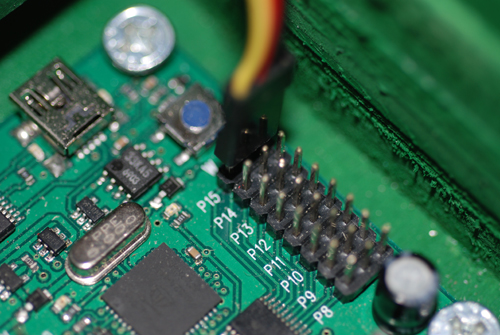
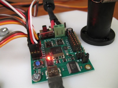
Step 25 - 26 Continue down the line, connecting the servo between the 6-hole and 5 hole support to P14, the servo between the 5-hole and 4-hole supports to P13, The servo between the 4-hole and 3-hole connector to P12, and the servo attached to the gripper hand to P11. |
 |
Step 27 |